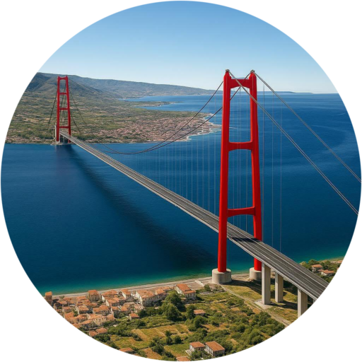
The cross-beam as shown in COWI's 2011 Detailed Design
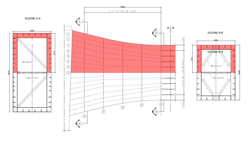
The cross-members connecting the two legs of each tower are located approximately at elevations of +125 m, +250 m, and +375 m. Each cross-member is 8 m wide and has a height varying between 11.5 m at the bridge centerline and approximately 22 m, 20 m, and 18 m at the leg face for cross-members 1, 2, and 3, respectively. The cross-members include the longitudinal and transverse stiffening steel plates for the webs and flanges. Typical cross-member cross-sections are shown in Figure 1.4. Each cross-member will be fabricated entirely in the shop and launched as a single piece on site. (Table PS0013 of the PD2011)
Other design references: cross-beam report in English PS0016, drawings of cross-beams 1, 2 and 3 respectively PS0027, PS0028, PS0029 and cross-beam details PS0030.
8
Counterwinds
A transverse bracing system, as shown in the drawing, is used to reduce the span lengths of the transverse stiffener and limit the stiffener's strength requirements. The bracing system consists of the following circular hollow sections: CHS 219.1×12.5, CHS 323.9×12.5, and CHS 406×16.
42
Stiffeners
Stiffeners As can be seen in the drawing, there are 30 transverse (type A and type B) and 12 longitudinal (type 1, 2 and 3).
1
Plate
6.20 m wide along the entire length at the centre of the crosspiece.
12
Gusset plates
Gusset plates 10 to attach the 8 braces and 2 at the opposite ends of the braces on the sides of the crosspiece to attach the plate to the final part.